  |
|
|
|
|
|
|
| |
|
|
|
|
|
|
What
do you think?
|
ELECTRONIC BASICS For Airsmiths by Bill Mills This article is the second in a series, beginning with the technical skill of soldering, and culminating with the knowledge needed for an airsmith to design, build and program their own microprocessor controller for use in paintball gear. In Electronic Basics we will focus on simple electronic theory, basic electronic components, what they do, and how they are represented in schematic drawings. For those of us who didnt sleep through all of our high school chemistry and physics classes, the idea that all matter is composed of atoms should not be a new one. Well cover this only very briefly. If this doesnt make too much sense, but you understand that electricity would flow through a wire connecting a pair of battery terminals, dont sweat the details. Molecules are the smallest piece of matter that retains that matters properties. For example, a water molecule, if broken apart will not be smaller pieces of water, but atoms of hydrogen and oxygen. Atoms are the smallest components of elements. There are 92 natural elements, and 10 or so more that have been man made. Most dont occur in pure atomic form in nature, they combine to form compunds (like water). The atoms themselves are made up of sub-atomic particles protons (positively charged), neutrons (no charge) and electrons (negatively charged). Protons and neutrons are in the center of the atom at its nucleus while electrons orbit around them. This is the part that concerns us the electrons. Why? Because they arent glued to the atom, they are somewhat loosely bound by an electric attraction. Its possible for an atom or molecule to have an excess of electrons - more electrons in its orbit than there are protons in its nucleus giving it a negative charge. It can also have a shortage of electrons, giving it a positive charge. These charges not only affect how atoms bond together to form molecular compounds, but also causes them to attract or repel any loose electrons.
This state of objects having electrical charges is referred to as potential. Electricity flows through different materials in different ways, and we call that electrical flow current. If they have a lot of loosely bound electrons, electricity can flow well, if they dont it wont flow well, but they can hold a charge, like the plastic comb. In general metals are good conductors, while plastics and organic materials dont conduct very well. Water is actually a very poor conductor, unless it has minerals and salts dissolved in it (like tap-water, or most anything but distilled pure water) in which case the minerals do a bang-up job which is why you shouldnt drop a TV in the bathtub with you. An ample unit of measurement Electrical current is measured in amperes, also called amps by people who dont like to type as many letters. As an analogy, amps are like gallons per minute of water its the raw volume of electrical current. For the kind of electronics well deal with in paintball well mostly work with milliamps, or mA. Scientific naming conventions are important, so I hope you were awake that day in chem class. Prefixes tacked on to a unit of measurement mean to multiply or divide it by some unit of ten, in order to have more manageable numbers with less zeroes around them. Lets look at some examples with amperes and some of the more common prefixes: 1 Megaamp (MA) = 1,000,000 amps
In electrical formulas I is the standard variable used to represent current, and unless another unit (i.e. mA) is given it is assumed that I is in amperes. This is revolting! The most widely known unit of electrical measurement is volts. Weve already envisioned current as how much electricity flows in a given amount of time, but what about that electrical potential we discussed earlier? Volts are the unit used to measure the difference in strength of electrical charges. That difference is there even when there is no electrical current flowing. In our river analogy, there is a big difference in how quickly water will run through a mellow stream across a gradually tilted plain compared to plunging headlong off of Niagra falls. In the same way, charges of higher voltages will draw more amperage. Volts are simply of a measure of how out of balance the electrical charges are. Volts are usually abbreviated to V as in a 9V battery. If were going to be all proper and snooty, E is how well represent voltage in an electronic formula, but be careful often people will write V when they mean E. Voltage in a circuit is measured with a volt meter connecting its leads to the to points between which there is potential. Watt, me worry? Back to our stream analogy. We could have a wide slow river like the Missippi, or a skinny slow river like a creek. We could also have a wispy waterfall like Bridalveil falls in Yosemite, or the aforementioned Niagra Falls. This combination of both potential and flow is power. Power is measured in watts, and its the total energy consumed in a circuit. In formulas, P represents power. Oh yeah, we can abbreviate it with you guessed it W. This leads to our first formula (Woohoo!) P=EI If we know the voltage of a power supply driving a circuit, and the amperage flowing through that circuit, we just multiply the two to get the wattage. With some simple algebraic substitution (you were right Mr. Semitsu, I would use this math stuff again someday) we can also solve for E or I. E=P/I and I=P/E How about some real world application? Say weve got a 60 watt lightbulb, and its screwed into a light socket in our ceiling that delivers 110 volts of power. To figure out how many amps of current the bulb draws, we just need to plug the numbers into the power formula. I=P/E I=60w/110v 0.55a = 60w/110v Power to go The power outlets in our homes in North America deliver about 110 volts (it varies a bit) of alternating current (the + and poles flip 60 times a second). Since we cant run a paintgun practically with an extension cord, and electronic circuits we will be dealing with all run on direct current from batteries, we can totally skip over all that AC stuff, and just focus on the direct current (DC) we get out of batteries. Quite simply batteries are containers filled with chemical goop called electrolyte that creates an electrical potential when exposed to the metals of the batterys poles. The type of electrolyte gives the battery its name. Alkaline batteries are disposeable as are Lithium Ion (Li) batteries. Nickel Metal Hydride (NiMH) and Nickle Cadmium (NiCad) batteries can be recharged as can the lead-acid batteries used in cars and motorcycles. One battery pole will have a surplus of electrons (a charge) while the other will have a shortage (a + charge.) All we have to do is provide a conductive path for the electrons and BAM weve got current. Different batteries have different characteristics. Most single cell consumer batteries (AAA, AA, C, D) have 1.5 volts of potential between their poles. The voltage is determined primarily not by the size of the battery, but by the material in the poles and the electrolyte. The amperage they can deliver is determined by the volume of the cell. I dont want to beat a dead horse, but lets look back at the river analogy. Say weve got a pair of rivers identical Econoloxahatchee Rivers (thats a river near Orlando with a name thats fun to say). If we run them side by side, they wont flow any faster (voltage the same) but well move twice as much water (amperage doubled). If we stack them one on top of each other, the starting point is now twice as high as before, so the flow rate will increase (voltage doubled) but the width of the banks wont get any wider, so our overall current will be the same.
Another consideration
of batteries also directly related to the volume of their cells, and
materials is amp hours. This is a simple rating of their ability
to deliver power over an amount of time before their charge is expended
and they lose their electrical potential (or at least to where it falls
below an acceptable voltage level). With consumer batteries, were
really dealing with milliamp hours. Since amp Let me draw you a diagram In a schematic,
a battery is represented either as a box, with the + and terminals marked
or as a series of dashes of alternating size - the side with the small
dash is the negative terminal. Another key symbol when dealing with
our power sources is the ground. Typically the ground is a common
circuit that ultimately is connected back to the terminal somewhere (unless
youre wiring a little British convertible that uses the arcane positive
ground). Especially in automotive uses, and sometimes in paintball
(the Wire, or circuit pathways on a printed circuit are represented in schematics as simple lines. They usually hop over one another in places where they cross, but are not connected. Something to keep in mind - schematic diagrams are meant to show how a circuit functions and do not necessarily reflect on how the components are organized on a finished circuit board. Resistance is futile Turning once again to the river, sometimes there are things that impede the flow of water through a river, like the weirs on the Kings River in central California. Thats resistance. The river is wide enough to handle a higher flow, and its got the potential, running downhill across the valley, but the weir dams things up a bit, and restricts the flow. In electrical circuits we call this resistance, and measure it in ohms, often written as the Greek letter Omega. Everything has resistance. In things we call non-conductors, like most plastics, resistance is very high, so it takes a very high potential to pass electricity through them. This is why people who arent such great conductors wont get shocked handling a 1.5v AA battery, but can get knocked down by the 110v current in a light socket. Conversely, in good conductors, like copper wire, resistance is very low and current will flow with high or low voltage. Electricity will always flow through the path of least resistance to get across an area of potential. This is really important to understand, because its the basis of a short circuit, which is basically electricity taking a short cut through a path of lower resistance that wasnt planned. For example, in a paintgun with a solenoid valve, if a scrap of metal comes in contact with the metal of the leads for the valve it will create a short circuit. When the paintgun tries to actuate the valve it releases a potential into the valve wires. The current goes through the scrap of metal instead of the solenoid since that path has less resistance, and the paintgun doesnt fire. In paintguns that use a chasis ground a short circuit between a positive charge and the chassis is called a ground fault. In formulas we represent resistance with an R. Ohms law relates current, voltage and resistance. E=IR We can also flip this around to I=E/R and R=E/I Just as often as we see straight Ohms, well be dealing with KiloOhms or MegaOhms which are abbreviated down to simply k, meg or M.
For cylindrical
resistors, learning the color codes can be a bit tricky. Many electronics
techs never memorize the whole codes, but recognize the color patterns
of resistors they commonly use. When looking at a resistor, there
are four color bands. Band one is closest to an edge, and bands 2,
3 and 4 are located progressively toward the other side.
Using this chart, its easy to read a resistor. A yellow-green-brown-silver resistor would be read as follows. The first two bands are yellow and green this translates to 45. The third band is brown, which means that the 45 must be multiplied by 10, giving the resistor a value of 450 Ohms. The fourth band indicates that the sorting tolerances allowed for +/- 10% error. That particular resistor might as much as 484 Ohms, or low as 405 Ohms. A lack of a fourth band would mean 20% tolerance. The cost of resistors goes up as the tolerances tighten.
CLICK HERE to continue to Part 2. |
| Copyright © 1992-2019
Corinthian Media Services. WARPIG's webmasters can be reached through our feedback form. All articles and images are copyrighted and may not be redistributed without the written permission of their original creators and Corinthian Media Services. The WARPIG paintball page is a collection of information and pointers to sources from around the internet and other locations. As such, Corinthian Media Services makes no claims to the trustworthiness or reliability of said information. The information contained in, and referenced by WARPIG, should not be used as a substitute for safety information from trained professionals in the paintball industry. |
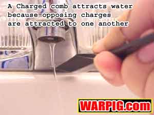 Electricity
is simply a flow of loose electrons from something that has a negative
charge to something that has a positive charge. If you run a comb
through your hair a few times it will likely develop a negative charge,
having dragged electrons out of the molecules that make up your hair.
If you hold it next to a thin stream of water running out of a faucet the
electronic attraction will actually bend the stream. If it touches
though, the electrons will flow into the water (the water is connected
through the pipes to the earth which can usually absorb negative charges
or provide electrons to cancel a positive charge) and the electrical charge
will be lost.
Electricity
is simply a flow of loose electrons from something that has a negative
charge to something that has a positive charge. If you run a comb
through your hair a few times it will likely develop a negative charge,
having dragged electrons out of the molecules that make up your hair.
If you hold it next to a thin stream of water running out of a faucet the
electronic attraction will actually bend the stream. If it touches
though, the electrons will flow into the water (the water is connected
through the pipes to the earth which can usually absorb negative charges
or provide electrons to cancel a positive charge) and the electrical charge
will be lost.
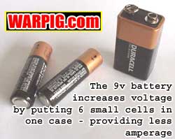
 The
9v alkaline battery can be a bit deceptive. Its actually a battery
made up of 6 individual cells in one package. These cells are put
together in series (end to end like the stacked Econoloxahatchee rivers
on top of each other) so we get six times the potential as a single cell.
We could also wire 6 AA batteries in series to do the same thing.
Our AA battery pack would deliver exactly the same voltage, but look at
the added volume it would have compared to the 9v. That would make
it capable of delivering more amperage. A prime example of this in
paintball, is the HALO loader, which needs more amperage to start its motor
than a 9v can deliver, and runs properly on 6 AA batteries in series.
The
9v alkaline battery can be a bit deceptive. Its actually a battery
made up of 6 individual cells in one package. These cells are put
together in series (end to end like the stacked Econoloxahatchee rivers
on top of each other) so we get six times the potential as a single cell.
We could also wire 6 AA batteries in series to do the same thing.
Our AA battery pack would deliver exactly the same voltage, but look at
the added volume it would have compared to the 9v. That would make
it capable of delivering more amperage. A prime example of this in
paintball, is the HALO loader, which needs more amperage to start its motor
than a 9v can deliver, and runs properly on 6 AA batteries in series.
 Another
way to beef up the available amperage from a battery pack is to wire cells
in parallel. If we took a pair of 9v batteries, linking the + and
terminals, wed be able to give twice the amperage to a circuit but still
stay at 9 volts (just like our rivers side by side.)
Another
way to beef up the available amperage from a battery pack is to wire cells
in parallel. If we took a pair of 9v batteries, linking the + and
terminals, wed be able to give twice the amperage to a circuit but still
stay at 9 volts (just like our rivers side by side.)
 hours
= amps * hours, the math concepts are easy here. A batterys life
will be cut in half if twice as many amps are drawn through it. Inversely,
if you wire two batteries in parallel, you double the milliamp hours available,
and double the service life of the batteries. In our pervasive water
analogy, milliamp hours would relate to the size of a mountain lake that
is feeding a river running down a mountainside. The larger the lake,
the more days the river can run before the lake is empty, and like a battery
must be recharged with a fresh supply.
hours
= amps * hours, the math concepts are easy here. A batterys life
will be cut in half if twice as many amps are drawn through it. Inversely,
if you wire two batteries in parallel, you double the milliamp hours available,
and double the service life of the batteries. In our pervasive water
analogy, milliamp hours would relate to the size of a mountain lake that
is feeding a river running down a mountainside. The larger the lake,
the more days the river can run before the lake is empty, and like a battery
must be recharged with a fresh supply.
 E-Mag
is an example) the ground circuit is a frame ground, meaning that the entire
chassis is connected to the ground circuit. This can make wiring
a bit easier, because anywhere you need to connect a circuit to ground,
you just make contact with the frame instead of running another wire.
E-Mag
is an example) the ground circuit is a frame ground, meaning that the entire
chassis is connected to the ground circuit. This can make wiring
a bit easier, because anywhere you need to connect a circuit to ground,
you just make contact with the frame instead of running another wire.
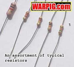 Resistors
are electrical components which have the sole purpose of resisting electrical
current. They are probably the most commonly used electrical component
in circuits. They are rated by both their resistance level, and how
much wattage they can handle being drawn through them. Larger wattage
resistors are bulky, in order to dissipate the heat they generate.
Half-watt, or even ¼, and 1/8 watt or smaller resistors are commonly
used in electronic circuits. Where lower current drains allow, even
smaller wattage resistors can be used. Using a resistor too small
for a particular circuit can be bad though, as it can burn out. Overkill
(using a large wattage resistor on a low wattage circuit) wont hurt the
circuit, but it will make things bulky.
Resistors
are electrical components which have the sole purpose of resisting electrical
current. They are probably the most commonly used electrical component
in circuits. They are rated by both their resistance level, and how
much wattage they can handle being drawn through them. Larger wattage
resistors are bulky, in order to dissipate the heat they generate.
Half-watt, or even ¼, and 1/8 watt or smaller resistors are commonly
used in electronic circuits. Where lower current drains allow, even
smaller wattage resistors can be used. Using a resistor too small
for a particular circuit can be bad though, as it can burn out. Overkill
(using a large wattage resistor on a low wattage circuit) wont hurt the
circuit, but it will make things bulky.
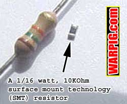 Resistors
are usually small cylinders with wire leads on each end. Color coded
stripes in the middle indicate their resistance levels. Compact circuitry
often uses Surface Mount Technology (SMT) resistors which are little more
than tiny chips with solder points on each side. Their resistance
is indicated by labeling on their package, as they are usually too small
to have resistance info painted on them.
Resistors
are usually small cylinders with wire leads on each end. Color coded
stripes in the middle indicate their resistance levels. Compact circuitry
often uses Surface Mount Technology (SMT) resistors which are little more
than tiny chips with solder points on each side. Their resistance
is indicated by labeling on their package, as they are usually too small
to have resistance info painted on them.
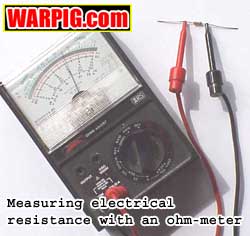 If
in doubt, the resistance of a resistor, or any component for that matter
can be measured by touching the leads of an ohmmeter to its leads.
Most electronic techs use multi-meters which measure not only resistance,
but voltage, as well.
If
in doubt, the resistance of a resistor, or any component for that matter
can be measured by touching the leads of an ohmmeter to its leads.
Most electronic techs use multi-meters which measure not only resistance,
but voltage, as well.