  |
|
|
|
|
|
|
| |
|
|
|
|
|
|
What
do you think?
|
The ShotMeter
Associated Files
Intro The ShotMeter is an ammo/CO2 tracking device that I built to discover if the “50 shots per ounce of CO2” myth is actually accurate. It took me about 6 hours to build the hardware and, so far, 2 months to write and debug the software. What the ShotMeter does:
I’m very happy with it and if you decide to build your own version I would be happy to try and provide any advice you may need. Why a ShotMeter? I play paintball… well, woodsball, mostly. One of my paintball peeves is not knowing how much CO2 is left in my tank. I ’ m usually in the middle of a pretty good scrap when suddenly my gas gives out and I ’ m eliminated with extreme prejudice! Unfortunately, there is no way to know exactly how many shots are left in a CO2 tank. The actual output of a tank varies due to ambient temperature and marker ( gun ) efficiency but a long-standing guesstimate of tank capacity is 50 shots per ounce of liquefied gas. Based on my own experience, I thought this estimate low and decided to find out just how true this fragment of conventional wisdom might be, so I built the ShotMeter! There were some project objectives I felt were very important. The unit had to:
Overall Concept As I thought about this project it occurred to me that I could build some extra functionality into the system outside of tracking how many shots into a tank I was. Why not estimate current loader ( motorized paintball feeder ) level and track overall shots for the day on the marker? Also, I could have the ShotMeter trigger the motorized loader with a simple relay! I wanted to track my loader level because I thought it might be pretty cool to have the ShotMeter tell me when the loader is low on paintballs by beeping at me and displaying a warning on the LCD. And, I wanted to track my overall shots per day because although I may bring 2000 rounds to the field I’ve been known to accidentally drop quite a few on the ground during an under-fire reload. I wanted to know how many paintballs I just plain lose. Triggering a loader would save me some money, too. A top-of-the-line loader could cost upwards of $120.00! With the loader trigger feature I could buy a cheap constant rotation loader for around $20.00 and connect a relay ( Figure A, K1) to control it. The load rate wouldn ’ t be very high, about 6-8 balls per second, but it would be cheap, very reliable, and have the same functionality as more expensive loaders when driven by the ShotMeter.
Nearly all electric loaders available today are triggered by either sound or infra-red beam interrupt technology. I didn ’ t want to duplicate a current product so I went with a magnetic field detector. Rather than a mechanical switch, like in a home alarm system, I decided a Hall Effect device would be ideal: no moving parts, an exceptionally small sealed case, and a very low current consumption. The unipolar Hall-effect sensor I chose is the OH090U manufactured by OPTEK ( Schematic, Q1) . This choice also allowed me to avoid altering the marker in asignificant way. Each time the south pole of a magnetic field comes near the front of this sensor the device sinks a 5-volt signal provided by a pull-up resistor ( Schematic, R6) . The sensor/magnet configuration on the marker is such that when the bolt is in the ready to fire position ( cocked back ) the south pole of the magnet is directly under the downward facing sensor, forcing the signal low. When the trigger is pulled and the bolt slams forward the loss of the magnetic field at the face of the sensor releases the signal. The release of the signal generates a low-to-high interrupt on the microprocessor's ( Schematic, U1) external interrupt pin, RB0. The interrupt service routine then causes the firmware to increment/decrement all of the related countsfor the device, check for any level warnings, beep if necessary, update the display ( Figure A, L1) , and engage the loader relay. I have added a new feature to the ShotMeter recently. The unit worked well the first time I went out with it but if I lost power for any reason, for instance if the loader cable disconnected, I lost all of the accumulated data. I needed a way for the unit to detect the start of a power failure and save the data before a complete power loss crashed the system. What I came up with is the use of an MCP120-475 ( Schematic U2) microprocessor supervisory device, made by Microchip Technologies, to detect the loss of power. As the main 5-volt power begins to drop, it crosses the 4.75 VDC tripping point for the device. When the device is tripped, it will sink the signal provided by a pull-up resistor ( Figure A, R7) on the LOWVOLT line, signaling the microprocessor to save all of the present values. The tricky part of this operation is that there has to be enough power left in the circuit to allow time for the processor to save the values before it crashes. A 470uF capacitor ( Schematic, C2) delays the power loss just long enough for the values to be saved on the microprocessors onboard EEPROM. Originally I was using a 220uF capacitor but as the battery began to wear the delay shortened and the microprocessor was only able to save two of the three required values. How It Operates On power-up the unit will display a title screen, beep for 0.5 seconds, agitate the loader for 0.5 seconds, and then display an option screen. The three options are: “ Setup ” , “ Clear Values ” , and “ Start ” . Each of these options corresponds to a button on the unit. The “ Start ” button accesses the values saved just before the last power-down and begins normal field operation of the unit using those numbers. Pressing the “ Clear Values ” button displays a short “ Values Cleared! ” message and zeros the values saved in memory and returns the user to the option screen. “ Setup ” takes the user through a setup procedure for all of the settings that are required for the ShotMeter to work properly. The setup procedure allows the user to:
The complete schematic of the ShotMeter is available as Figure A in the .PDF format accompanying this article. The elements in the dashed boxes are off-PCB sub circuits: the loader internals, the sensor assembly, and the button assembly. Note that the capital letters are corresponding connection points between the main PCB and the sub circuits
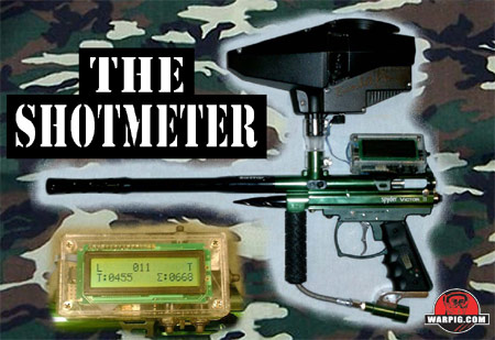
“T:0455” and shots for the day “Ó:0668” totals. The button on top of the ShotMeter is the on/off switch (O), the button on the right face is the Tank (T) button, the left button on the bottom face is the Loader button (L), and the right button on the bottom face is the Pod button (P).
The basic operation of the unit is this:
What the operator can do when a warning occurs:
Constructing the ShotMeter As you may imagine, the paintball field is not an ideal place for electronics. There ’ s plenty of dirt and lots of physical shock from running and dodging but the main hazard to field electronics is the paint itself. The paint is water-based and I felt that could be detrimental to proper field operation. The problem was that I didn ’ t know exactly how dangerous it might be.
The globs were all roughly 1 inch across and between 0.13 ” and 0.5 ” high. The resistance of the globs measured between 3.69 and 16.37 MÙ. Though resistances that high probably won ’ t cause a fatal smoking short it could make trouble for digital data signals and capacitors. I found it interesting that the thickness of the paint seemed to be directly proportional to the resistance exhibited. Paintballs, which usually travel at between 250 and 300 feet per second, tend to shoot their insides through remarkably small gaps in things when they strike. I found rubber covers ( boots ) for my buttons and housed the unit in a transparent ABS plastic enclosure. I filed a shallow groove for the wire access in the enclosure lid and body with a fine finishing file. The ribbon cables are lightly pinched between the enclosure lid and body. The holes for the buttons were drilled on a standard drill press using a 0.25” bit. I couldn’t find a through-hole mounted piezo beeper small enough to fit inside so I affixed a surface mount beeper ( Schematic, LS1) to the wall of the enclosure with double-sided tape and ran wires from the beeper to the microprocessor.
I used a “ super strong ” neodymium magnet I happened to have stuck on my refrigerator to activate the sensor. I have no idea where I got this specific magnet but I have seen similar ones at craft and hardware stores. The magnet is slightly less than 0.25” in diameter and 0.13 ” high and fits conveniently into the top of a hole bored through the aluminum bolt . The top 1/4 of this hole is empty which allows the magnet to fit snuggly within. Also, the steel of the pin provides an excellent magnetic bond which keeps the magnet in place during those violent bolt cycles; no adhesive necessary! Further, because the marker body is also aluminum the magnet isn ’ t attracted to it and the magnetic field passes through it with little degradation. Modifying the Loader The loader I chose to use is a Ricochet Rhino ( Figure E, topmost part of the marker ) which I picked up for $22.00 on-line. I chose this loader for two reasons: it ’ s very inexpensive and it has a great look to it. What I did was use a 2.5mm stereo ( Schematic, J4 ) headphone jack as the connector from theShotMeter. I drilled a 0.25” counter-sunk hole through the bottom of the motor compartment. I disconnected the battery from the loaders original control circuit by cutting the ground trace to the rest of the nearly unpopulated printed circuit board ( PCB ) . Then I soldered wires to the edge of the battery contacts on the original PCB and ran those wires to the headphone jack; positive to the tip and ground to the sleeve. Next, I cut the connector from the end of the motor leads and connected the red wire to the battery positive contact and the black wire to the ring contact of the headphone jack. The relay in the ShotMeter grounds this ring contact wire to make the motor rotate. Also, I added a noise filtering cap and a clipping diode ( Schematic A, C5, D1) to the motor to mitigate any possible noise or back EMF issues. For a complete schematic and parts list, download the .PDF file linked at the beginning of this article. The Firmware When I started the project I tried to use a PIC 16F628 I had in my parts box. Unfortunately, there was barely enough program space to house the minimum features I wanted and no room for hardware expansion. I then upgraded to the PIC16F876 processor by Microchip Technologies because it has plenty of program space, more I/Os than I need, and an internal EEPROM I could save settings on. The program itself currently requires only about half of the total memory available. I listed a bit of code I thought might help some fellow tinkerers out there with their own projects. The code ( See the .PDF Schematic linked above. ) is a way to show a bar-graph style display on the second line of an LCD. This program listing was originally written in MBasic Pro from Basic Micro but I’ve stripped out the MBasic specific parts to make it more “ pseudo-code. ” The complete MBasic Pro file, which could be a good blueprint for those interested in creating their own ShotMeter, as well as the PIC .hex file can be downloaded from the links provided by Warpig.com. Please take note that the line names on the schematic match variables or constants in the program; e.g. the LOWVOLT line on the schematic corresponds to the LOWVOLT i/o constant in the program. ShotMeter Limitations The ShotMeter is only as accurate as the operator makes it. I for one will not be ensuring that every pod has exactly 100 paintballs in it or the loader is always topped off with exactly 170 balls. The loader level and the shots/day ball counts will continually be best-guesses as these are indirect counts; the ShotMeter counts cycles of the bolt whether there is a ball in the breach or not. The tank count will be accurate as it is based on the bolt cycles themselves and meant to measure gas used rather than paintballs. The Data After comparing the shots per day to the number of paintballs I brought to the field, I found that when I do lose balls, I usually drop 100-300 a day. In regards to the "50 shots per ounce" estimate, it seems that this approximation is notably low. The data in the Shot Meter Data chart was collected over 3 days of play with temperatures between 75 and 98 degrees Fahrenheit. The calculated average based on teh collected data is 86 shots per ounce! More than half again as many shots per ounce than the long standing estimate had indicated.
Next Steps As the current version of the circuit is a hand soldered proto-board my next step may be to port everything over to a smaller surface mount design and free-up some room inside the enclosure for another upgrade or two: perhaps a digital compass or ballistic trajectory calculator. Or, I may just try to make it as small and light as possible. I've found the "ammo low" warning to be helpful on the field, and knowing approximately how far into a tank I am has been very handy, as well. I hope you have found this project interesting and useful. Please contact me with any questions or comments at the e-mail address listed in the beginning of this article.
|
| Copyright © 1992-2019
Corinthian Media Services. WARPIG's webmasters can be reached through our feedback form. All articles and images are copyrighted and may not be redistributed without the written permission of their original creators and Corinthian Media Services. The WARPIG paintball page is a collection of information and pointers to sources from around the internet and other locations. As such, Corinthian Media Services makes no claims to the trustworthiness or reliability of said information. The information contained in, and referenced by WARPIG, should not be used as a substitute for safety information from trained professionals in the paintball industry. |

 The Hall Effect
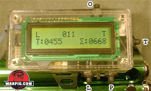 Figure B: This is the 16x2 display in the standard tracking mode. Top line (left to right): loader low warning “L”, loader level count “011”, and tank low warning “T.” Bottom line (left to right): shots used from tank
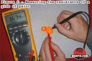 After breaking open several paintballs from different manufacturers onto a plastic cutting board ( Figure C ) I measured the resistance across each glob of paint.
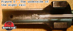 The Hall-Effect sensor is set in a pair of shallow overlapping holes ( 0.25 ” diameter by less than 0.25 ” deep ) I drilled into the bottom of the sight rail. I then covered the sensor with hot glue to keep it in place and ward off any moisture. I ran the sensor wires under the site rail and up the front face and then into the ShotMeter.
 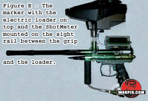 The completed assembly is mounted on the sight-rail via a home-made aluminum bracket.
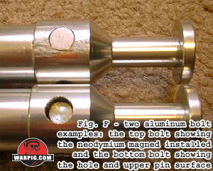 The hole is mostly filled with the upper half of a steel pin, the bolt pin, that sticks out the bottom of the bolt.