  |
|
|
|
|
|
|
| |
|
|
|
|
|
|

PigTV Magna Drive Loader Interview Video
Product Testing performed with DraXxus Paintballs What
do you think?
|
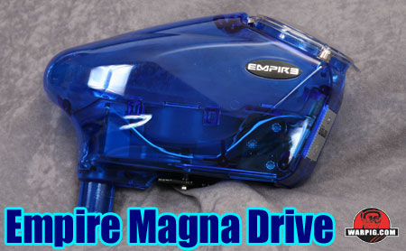
Empire Magna Drive Loader
Continued from PAGE 1. The Magna Drive loader offers configuration options both at the hardware and software levels. The breaking strength of the magnetic clutch is adjustable as are multiple settings in the control software. Of the two types of adjustment, the electronic is simpler to achieve, as it is done through the power button, and does not require disassembly of the loader.
The screws holding the loader halves together are tapered, and screw into the polycarbonate of the left shell-half, unlike the HALO and earlier Reloader designs, where the opposing half had hexagonal slots allowing for steel nuts, reducing the chance of a stripped body losing its grip on a screw. Because of this, greater care will need to be taken on reassembly to ensure that the screws are snug, but not over-tightened. Also unlike earlier models, all loader body screws are the same length, avoiding confusion over which screw goes where.
A single Phillips screw in the center of the drive cone assembly holds it in place. Its removal allows the entire drive cone assembly to be lifted out. For reassembly or clutch adjustment the magnet holder is first reinstalled on the drive shaft.
In the stock configuration, four magnets are installed in the inner ring, and three in the outer points. Additional magnets are packaged with the loader to allow for a tighter clutch configuration.
The drive cone sits on top of this, and must be pre-wound, by rotating it clockwise until the spring cup and drive cone's spring tabs bump into each other. The drive cone is lifted slightly, and rotated more until the spring tabs pass each other.
The loader is reassembled in the reverse order of disassembly, with care taken to ensure that the lid magnet is seated, and the battery door is properly aligned. Electronic adjustment of the Magna Drive Loader allows for configuration of the motor speed, microphone sensitivity and spring tensioning setting.
In programming mode, the LED flashes green, with the number of flashes indicating the motor speed setting from 1 to 6. This setting controls the current pulses delivered to the motor, quite literally controlling how fast it, and thus the drive cone assembly will turn. The default setting is 4. Testing of the loader was performed both at the stock setting, and the maximum speed of 6. The LED then flashes orange, with the number of flashes indicating the microphone sensitivity setting, which can range between 1 and 6. Theoretically, if set too high, this could cause the loader to activate more often than is needed, and if set too low, it would not activate and feed when the marker is fired. The factory setting of the loader reviewed was 6 – the most sensitive, and it had no trouble activating with a Matrix LCD and Shocker NXT during testing. The final setting is spring tension monitoring, in which the electronics use the load on the motor as feedback to determine of the drive cone is free spinning, or facing resistance, resulting in reduced battery use. The default setting is on (2 flashes.) Each of the setting can then be changed by waiting for the LED to show the setting color, and pressing the power/programming button the number of times for the desired value. Both assembly and programming instructions were clearly covered in the loader's 20-page color illustrated manual. This manual was surpsisingly thorough, compared to other loader manuals. To test the Magna Drive Loader's performance it was put through both the WARPIG Ballistic Labs standardized 10-shot burst and 14-shot ramping feed tests.
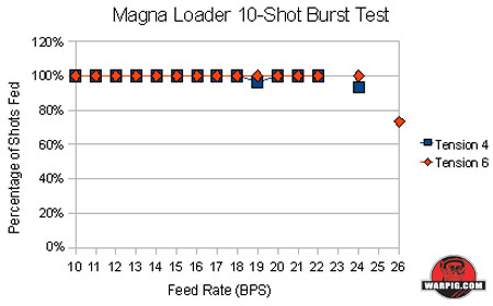
The 10-shot burst test involves firing three 10-shot bursts at test rates of fire, and then continuing to the next higher rate if at least two of the three bursts fed flawlessly. This test is particularly demanding for loaders, and does not indicate the maximum rate at which a loader may feed, but rather the maximum rate that a loader may sustain over 10 shots, after starting from a dead-stop. At the stock settings, the loader fed flawlessly from 10 up through 18 balls per second. At 19 bps, one of the three trials only fed 9 balls, but the other two trials fed all 10. The loader continued to feed without error at rates up to 22 bps, at which point, due to timing constraints of the microcontroller used for testing, trials are performed at even numbered rates of fire.. Skipping 23, the test performed at 24 bps resulted in two trials that only fed 9 paintballs and one trial that fed 10. A test score of 22bps was faster than any prior loader subjected to this test.
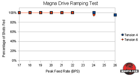
After adjusting the loader's speed to the maximum setting of 6, the loader fed all paintballs in all trials from 10 through 24 balls per second, and skipped shots in each of the three trials performed at 26 balls per second, yielding another record breaking score of 24 bps. The 14-shot ramping test similarly checks for maximum rates of fire that can be sustained over 10 shots, but instead of starting the loader from a dead-stop, it is given a chance to ramp up to speed by first firing four shots at a rate of 10 balls per second. In the ramping test, at the stock settings, the loader feed flawlessly up to 24bps, but could not pass at 26. Surprisingly, when the motor speed was increased to 6, the loader fed with out error up to 22 bps, but could not pass at 24 bps.
Additional ad-hoc test cycles were run at both motor speed settings with identical results, confirming the relationship between motor speed and top score in the ramping test. For result data from individual test trials, click here. While it may seem counter-intuitive that the higher speed setting produced a lower performance score, the test results support the concept that raw motor speed alone is not the only factor involved in fast loading of paintballs. For loader designers, increasing loader performance is not as simple as using a faster motor. In both standardized test formats, the Magna Drive Loader set new records, by a significant margin. As the next evolutionary step in the HALO/Reloader line, the Magna Drive loader features an innovative new magnetic clutch system, and improved levels of adjustability, while an easier to handle battery hatch and significant improvements in performance making it stand out from the crowd.
|
| Copyright © 1992-2019
Corinthian Media Services. WARPIG's webmasters can be reached through our feedback form. All articles and images are copyrighted and may not be redistributed without the written permission of their original creators and Corinthian Media Services. The WARPIG paintball page is a collection of information and pointers to sources from around the internet and other locations. As such, Corinthian Media Services makes no claims to the trustworthiness or reliability of said information. The information contained in, and referenced by WARPIG, should not be used as a substitute for safety information from trained professionals in the paintball industry. |

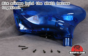 Adjusting the Magna Drive clutch requires opening the Magna Drive Loader. This is achieved by first removing the battery pack, and then taking the screws out of the right side shell half. Here, another departure from the HALO loaders is noticeable.
 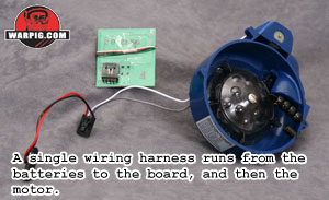 With the screws removed, the two loader halves can be carefully pulled apart leaving the internal components in the left shell half. During disassembly it is important not to lose the lid magnet held between the two body halves near the lid hinge. At this point, most internal components are directly accessible for removal. The deck can be swapped out (if the components were left in the right half, the drive system would interfere with removal or installation of the extended deck) as can the circuit board or drive train.
 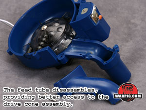 A pair of screws may be removed to release the upper half of the feed tube. This piece may next be lifted away, to make room for the drive cone assembly to be lifted out for clutch adjustment.
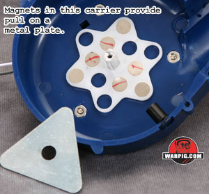 The magnet holder is shaped like a Star of David with 12 holes for magnets, arranged in an inner ring of 6, and an outer ring of 6 (the points of the star.) When magnets are placed in the inner ring of holes, they provide a constant gripping force against the triangular metal clutch plate, because while the plate rotates, the same number of magnets are aligned with it.
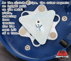 Placing magnets in the outer holes creates a friction that decreases when the clutch slips. Once a triangle point is pulled off of a magnet, the magnet offers no resistance until it lines up with the next triangle point.
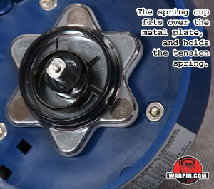 After re-configuring magnets to change clutch resistance characteristics, the metal plate is greased lightly and installed on the drive axle, followed by the spring cup and spring.
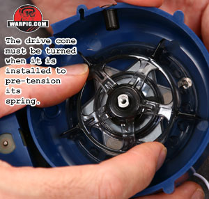 The drive cone is then pressed down, and topped with the drive cone cover, and secured with the drive cone screw.
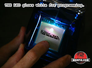 When the loader turns on, its power-up sequence includes the LED flashing white. Pressing the power button while the LED is white enters the programming mode.
 Both tests involved filling the loader with 100 DraXxus Hellfire paintballs and running the marker on a Matrix LCD receiver, cycling without a barrel into a ball decelerator to catch and verify the number of paintballs fed through the marker without damage or breakage. For the testing, the Matrix receiver is controlled by a custom controller circuit set to fire at precise rates.