Nerve
By Bill Mills - Jan 2005
Photos By Dawn Mills
Page1
Page2 Chrono
Data
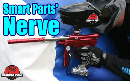
After more than a year of anticipation,
Smart Parts released the Nerve in the fall of 2004. This new paintgun
has been poised to take the position of flagship in the companys offerings
for tournament level paintball guns. While many expected something
radically different in concept from the companys previous paintguns, the
final product took the operating concepts found in the successful Impulse
design, and made them more compact, reliable and faster.
 From
the get-go, the Nerve is designed to be an out of the box performer.
Its design philosophy is that a top of the line tournament paintgun should
include all of the bells and whistles. If all of the components used
are top of the line, there should be no need to spend additional money
on upgrades and accessories. From
the get-go, the Nerve is designed to be an out of the box performer.
Its design philosophy is that a top of the line tournament paintgun should
include all of the bells and whistles. If all of the components used
are top of the line, there should be no need to spend additional money
on upgrades and accessories.
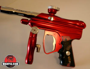
The layout of the Nerve is slightly
taller and narrower than Smart Parts Shocker SFT, and noticeably smaller
than the Impulse from which it descended. The stacked tube design
is milled with a wavy, organic look. In its upper half it houses
the bolt which chambers each paintball and seals the breech against the
Seal Forward Technology o-ring, and the lower half it contains the valve,
as well as the hammer, low pressure regulator and pneumatic ram.
The Nerves grip frame holds the trigger, electronics, and the solenoid
valve, which translates electrical signals into low-pressure gas flow for
operation of the valve.
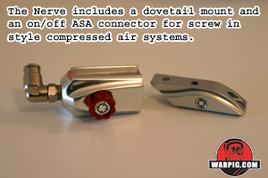 As
shipped, the Nerve includes a small drop forward mount, and a Smart Parts
on/off ASA valve, ready to accept a screw in style compressed air system.
It is also available bundled with Smart Parts Inline Max Flo compressed
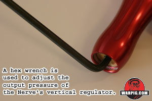
air system. Either setup feeds gas into the Nerves vertical regulator
which serves double duty as the guns foregrip. The regulator connects
to the Nerve with an ASA fitting, giving players the option of switching
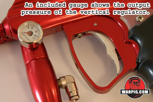
to an aftermarket regulator if they so choose. Included in the ASA
is a 0 to 300 psi pressure gauge making it easy to set the vertical reg.
Typical set-up is in the range of 240 to 300 psi. As
shipped, the Nerve includes a small drop forward mount, and a Smart Parts
on/off ASA valve, ready to accept a screw in style compressed air system.
It is also available bundled with Smart Parts Inline Max Flo compressed
air system. Either setup feeds gas into the Nerves vertical regulator
which serves double duty as the guns foregrip. The regulator connects
to the Nerve with an ASA fitting, giving players the option of switching
to an aftermarket regulator if they so choose. Included in the ASA
is a 0 to 300 psi pressure gauge making it easy to set the vertical reg.
Typical set-up is in the range of 240 to 300 psi.
 The
gas from the vertical regulator feeds directly to the valve in the lower
receiver. It also is fed to a low pressure regulator in the front
of the body. The LPR drops gas pressure further, and routes it back,
through internal ducts (it is a hose-free design) to a manifold on the
bottom of the receiver. There, the solenoid valve re-routes gas into
one of two ports, to operate the firing piston assembly. The
gas from the vertical regulator feeds directly to the valve in the lower
receiver. It also is fed to a low pressure regulator in the front
of the body. The LPR drops gas pressure further, and routes it back,
through internal ducts (it is a hose-free design) to a manifold on the
bottom of the receiver. There, the solenoid valve re-routes gas into
one of two ports, to operate the firing piston assembly.
 It
is the Nerves firing piston that makes its design a departure from the
typical stacked tube electropneumatic paintgun. Rather than a ram
which sits at the back of the gun and drives a hammer forward into the
valve, the Nerves ram actually sits in the middle of the assembly, between
the valve and the hammer. The central core of the ram still strikes
forward into the valve, but the mass of the hammer, and the link to the
Nerves bolt rides on the backside of the ram. This arrangement helps
make the Nerve more compact, while still capable of high rates of fire. It
is the Nerves firing piston that makes its design a departure from the
typical stacked tube electropneumatic paintgun. Rather than a ram
which sits at the back of the gun and drives a hammer forward into the
valve, the Nerves ram actually sits in the middle of the assembly, between
the valve and the hammer. The central core of the ram still strikes
forward into the valve, but the mass of the hammer, and the link to the
Nerves bolt rides on the backside of the ram. This arrangement helps
make the Nerve more compact, while still capable of high rates of fire.
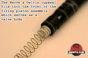 The
actual valve body is a part of the piston housing. The entire valve
body and piston assembly removes from the receiver as a single unit for
maintenance. Completing the valve is a traditionally styled valve
core in which the pin and cup seal are machined out of a single piece of
Delrin. Because the valve pin actually rides inside the hollow front
end of the piston, mushrooming or other deformation of the valve pin from
impacts is minimized. The
actual valve body is a part of the piston housing. The entire valve
body and piston assembly removes from the receiver as a single unit for
maintenance. Completing the valve is a traditionally styled valve
core in which the pin and cup seal are machined out of a single piece of
Delrin. Because the valve pin actually rides inside the hollow front
end of the piston, mushrooming or other deformation of the valve pin from
impacts is minimized.

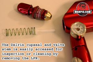 Access
to the valve core for inspection or replacement is as easy as with most
stacked tube blowback semis the LPR is removed from the front of the
receiver, and pulling out the valve spring takes the core with it.
This is much simpler than valve access with most electropneumatic paintgun
designs. Access
to the valve core for inspection or replacement is as easy as with most
stacked tube blowback semis the LPR is removed from the front of the
receiver, and pulling out the valve spring takes the core with it.
This is much simpler than valve access with most electropneumatic paintgun
designs.
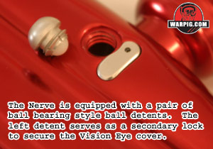 In
the breech of the Nerve lies another of its standard features an anti-chop
infrared emitter and detector Smart Parts calls Vision. Unlike Smart
Parts other paintguns, the Nerve does not ship without Vision. The
Vision eye is fully integrated into the Nerve receiver. A small flat
aluminum cover locked in place by the left side ball detent is the only
external sign of the eye. There are no bulky eye wire covers, or
exposed wires. In
the breech of the Nerve lies another of its standard features an anti-chop
infrared emitter and detector Smart Parts calls Vision. Unlike Smart
Parts other paintguns, the Nerve does not ship without Vision. The
Vision eye is fully integrated into the Nerve receiver. A small flat
aluminum cover locked in place by the left side ball detent is the only
external sign of the eye. There are no bulky eye wire covers, or
exposed wires.
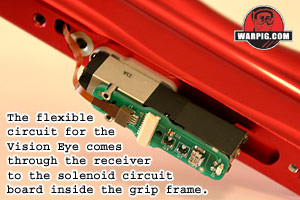
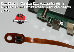 The
flexible ribbon circuit running from the Vision eye to the Nerves circuit
board is routed through internal paths in the receiver. The advantage
to this layout is clear, the circuit is fully protected inside the gun
and not subject to wear, snagging on any part of the field or breaking
from impacts by a paintball. The integrated layout does come with
a small price however. The circuit passes through the lower receiver
around a cut out in the firing piston assembly. In order to slide
the firing piston assembly out for maintenance the Vision eye must first
be removed. The
flexible ribbon circuit running from the Vision eye to the Nerves circuit
board is routed through internal paths in the receiver. The advantage
to this layout is clear, the circuit is fully protected inside the gun
and not subject to wear, snagging on any part of the field or breaking
from impacts by a paintball. The integrated layout does come with
a small price however. The circuit passes through the lower receiver
around a cut out in the firing piston assembly. In order to slide
the firing piston assembly out for maintenance the Vision eye must first
be removed.
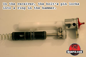 Field
stripping the Nerve has been made incredibly simple. The guns Delrin
bolt is linked to the hammer in the lower receiver by a steel pin in the
back of the bolt. Rather than having to remove the pin through the
top as with many stacked tube designs, the Nerve is built so that the bolt
can be rotated, about one eighth of a turn clockwise. This disengages
the link pin from its slot in the hammer. Field
stripping the Nerve has been made incredibly simple. The guns Delrin
bolt is linked to the hammer in the lower receiver by a steel pin in the
back of the bolt. Rather than having to remove the pin through the
top as with many stacked tube designs, the Nerve is built so that the bolt
can be rotated, about one eighth of a turn clockwise. This disengages
the link pin from its slot in the hammer.
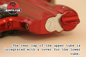 In
a very clean arrangement the bolt nestles into an end cap in the back of
the Nerve when it is open and the gun is at rest. A thumb knob which
forms the end cap rests in the top of a backplate that covers the rear
of the receiver. Twisting the knob clockwise simultaneously unlocks
the end cap from a pair of steel pins in the receiver, rotates the bolt
to unlock it from the hammer, and captures the bolt in the rear cap. In
a very clean arrangement the bolt nestles into an end cap in the back of
the Nerve when it is open and the gun is at rest. A thumb knob which
forms the end cap rests in the top of a backplate that covers the rear
of the receiver. Twisting the knob clockwise simultaneously unlocks
the end cap from a pair of steel pins in the receiver, rotates the bolt
to unlock it from the hammer, and captures the bolt in the rear cap.
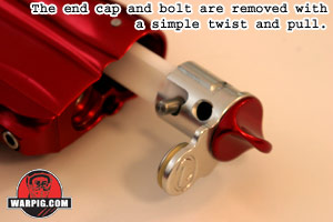 The
result of the design is that one quick move is all that is needed to twist
the cap, unlocking it, and pull off the end cap, as well as remove the
bolt. This leaves the bolt free for inspection, the receiver and
barrel of the Nerve available for cleaning with a pull-through squeegee,
and the hammer visible for inspection. Spring loaded ball bearing
detents index the end cap either into the locked or unlocked position,
so that it wont work its way loose on the field. The
result of the design is that one quick move is all that is needed to twist
the cap, unlocking it, and pull off the end cap, as well as remove the
bolt. This leaves the bolt free for inspection, the receiver and
barrel of the Nerve available for cleaning with a pull-through squeegee,
and the hammer visible for inspection. Spring loaded ball bearing
detents index the end cap either into the locked or unlocked position,
so that it wont work its way loose on the field.
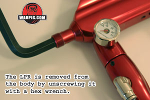 A
full bench disassembly of the Nerve does not take long, nor is it unusually
complex. It begins with degassing the gun, then field stripping of
the bolt assembly. The LPR is removed by first unscrewing its knob
(which provides access to its internals for inspection) and then removing
it by inserting a large hex wrench in its center and unscrewing.
The valve spring and core are then removed from the receiver. A
full bench disassembly of the Nerve does not take long, nor is it unusually
complex. It begins with degassing the gun, then field stripping of
the bolt assembly. The LPR is removed by first unscrewing its knob
(which provides access to its internals for inspection) and then removing
it by inserting a large hex wrench in its center and unscrewing.
The valve spring and core are then removed from the receiver.
 The
grip frame is removed from the receiver by taking out the two grip frame
screws, and unplugging the wire harness leading to the solenoids circuit
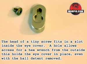
board. The Vision Eye cover is then removed by first taking off the
ball detent which overlaps its top, and then inserting a small hex wrench
in an access hole in the top of the cover to unscrew the covers lock screw. The
grip frame is removed from the receiver by taking out the two grip frame
screws, and unplugging the wire harness leading to the solenoids circuit
board. The Vision Eye cover is then removed by first taking off the
ball detent which overlaps its top, and then inserting a small hex wrench
in an access hole in the top of the cover to unscrew the covers lock screw.
 With
the eye visible, it can be unplugged from the solenoid circuit board, and
simply lifted out of the receiver. Removal of the eye is critical
to prevent its ribbon circuit from being damaged as the firing piston assembly
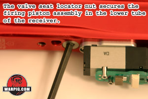
is removed. With the eye set aside, the valve seat locator nut, which
locks the firing position in place, can be removed with a hex wrench. With
the eye visible, it can be unplugged from the solenoid circuit board, and
simply lifted out of the receiver. Removal of the eye is critical
to prevent its ribbon circuit from being damaged as the firing piston assembly
is removed. With the eye set aside, the valve seat locator nut, which
locks the firing position in place, can be removed with a hex wrench.
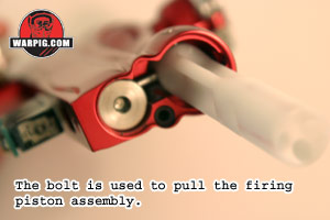 Once
the firing piston assembly is unlocked, it is easily removed from the back
of the receiver by using the bolt as a tool. The bolt can be inserted
backwards into the upper bore of the receiver, and the bolt pin engaged
into the hammer. Pulling back on the bolt will bring the hammer and
firing piston assembly with it. Once
the firing piston assembly is unlocked, it is easily removed from the back
of the receiver by using the bolt as a tool. The bolt can be inserted
backwards into the upper bore of the receiver, and the bolt pin engaged
into the hammer. Pulling back on the bolt will bring the hammer and
firing piston assembly with it.
Assembly is a reverse of the disassembly
process. Once the firing piston assembly is locked back in place
with the locator nut, the vision eye ribbon practically guides itself through
the receiver after being fed into the hole at the eye location. The
LPR can be reassembled and then screwed into the front after the valve
core and spring are dropped into place.
Go To Next Page
|