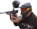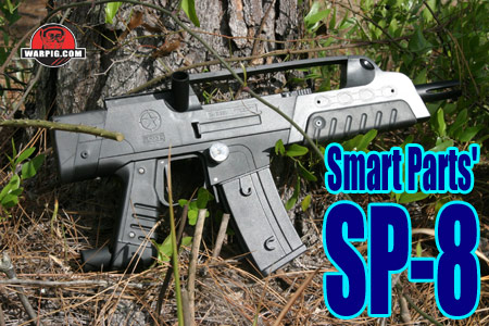
SP-8
By Bill Mills - Photos
by Dawn Mills - Apr 2006
Disassembly
Overview
- How It Works - Disassembly
- Testing - Raw Test Data
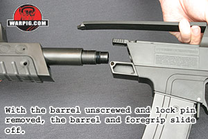
Field stripping the SP-8 is basically
limited to pulling the barrel and foregrip for cleaning. While only
the muzzle is normally exposed, the SP-8s barrel is removed just like
that of most paintguns, it unscrews and then slides forward out of the
foregrip.
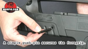 A
single push-pin locks the foregrip in position. The pin is friction
fit with a small o-ring to keep it from falling out. A stick, screwdriver
or hex wrench can be used to press the pin out, allowing the foregrip to
slide off to the front. A
single push-pin locks the foregrip in position. The pin is friction
fit with a small o-ring to keep it from falling out. A stick, screwdriver
or hex wrench can be used to press the pin out, allowing the foregrip to
slide off to the front.
Disassembling the SP-8 much further
is a task for the staging area, or the workbench. It starts with
unloading and degassing the marker.
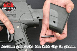 Another
push-pin holds the butt-cap on the back of the receiver. Sliding
this out and removing the butt-cap leaves the grip frame screws connecting
the grip frame and upper receiver. Another
push-pin holds the butt-cap on the back of the receiver. Sliding
this out and removing the butt-cap leaves the grip frame screws connecting
the grip frame and upper receiver.
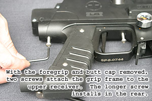 One
screw is located at the back of the grip frame and the other lies just
forward of the trigger. They are removed with a hex wrench.
It is important to note that the rear screw is longer than the front screw.
The receiver can then be lifted away from the grip frame. As with
the ion, the wiring harness of the Vision eye, and the gas fittings to
the fire chamber, front body breech and circuit board will keep the receiver
and grip frame from coming far apart. One
screw is located at the back of the grip frame and the other lies just
forward of the trigger. They are removed with a hex wrench.
It is important to note that the rear screw is longer than the front screw.
The receiver can then be lifted away from the grip frame. As with
the ion, the wiring harness of the Vision eye, and the gas fittings to
the fire chamber, front body breech and circuit board will keep the receiver
and grip frame from coming far apart.
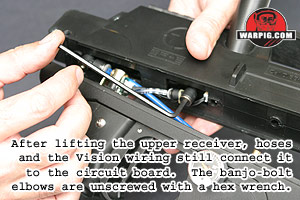 A
hex wrench is then used to remove the two banjo bolt air fittings from
the front body breech and the swivel donut on the back of the fire chamber. A
hex wrench is then used to remove the two banjo bolt air fittings from
the front body breech and the swivel donut on the back of the fire chamber.
Because these are banjo style elbows,
their centers pivot, so they can be unscrewed without having to twist the
hoses to which they are connected.
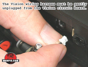 The
Vision cable is easily removed from the vision circuit board taking care
to remove the plug, not just tug on the wires, as this can eventually yank
them out of the plug. A small o-ring pick or similar tool can help
with this operation. The
Vision cable is easily removed from the vision circuit board taking care
to remove the plug, not just tug on the wires, as this can eventually yank
them out of the plug. A small o-ring pick or similar tool can help
with this operation.
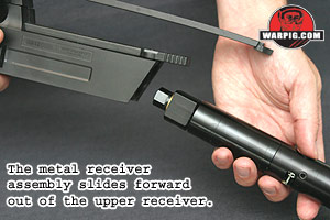 The
metal receiver consisting of the fire chamber and front body breech can
then be slid out the front of the upper receiver. The Vision circuit
board, located in the bottom of the front body breech might cause a problem
here. If it slides just a little bit out of place, it can catch on
the upper receiver, so it is important not to force the inner receiver
out if it feels like it is not sliding readily. It is imperative
to make sure the vision board is seated all the way in the front body breech
and not catching on the upper receiver. The
metal receiver consisting of the fire chamber and front body breech can
then be slid out the front of the upper receiver. The Vision circuit
board, located in the bottom of the front body breech might cause a problem
here. If it slides just a little bit out of place, it can catch on
the upper receiver, so it is important not to force the inner receiver
out if it feels like it is not sliding readily. It is imperative
to make sure the vision board is seated all the way in the front body breech
and not catching on the upper receiver.
 With
the internal metal receiver free, it is easy to see that the SP-8 is so
much an Ion on the inside. The fire chamber is the same, and the
swivel donut and front body breech are nearly identical. The swivel
donut on the back, which is what feeds air to the fire chamber, while swiveling
to account for thread alignment on the front of the fire chamber is more
rectangular than that of the Ion, in order to fit properly in the upper
body receiver. With
the internal metal receiver free, it is easy to see that the SP-8 is so
much an Ion on the inside. The fire chamber is the same, and the
swivel donut and front body breech are nearly identical. The swivel
donut on the back, which is what feeds air to the fire chamber, while swiveling
to account for thread alignment on the front of the fire chamber is more
rectangular than that of the Ion, in order to fit properly in the upper
body receiver.
The front body breech is not threaded
for a feedneck, because the SP-8s feedneck is held in place by the upper
receiver. Also its exterior texture is smooth rather than matte like
the Ions other than that it is Ion style. The fire chamber itself
is interchangeable with that of an Ion and even shares the same part number.
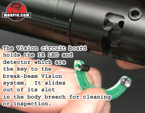
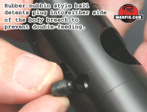
It is easy to lift out the C-shaped
Vision eye board from the front body breech for cleaning and inspection.
The rubber nubbin style ball detents can also be similarly removed for
cleaning or replacement if needed.
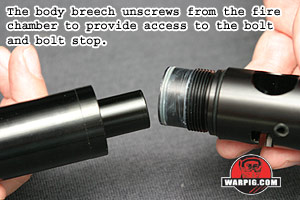
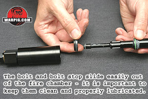 Only
hand strength is needed to unscrew the front body breech from the fire
chamber. This allows the bolt and bolt stop to be pulled out so their
seals can be cleaned, lubricated and inspected. Only
hand strength is needed to unscrew the front body breech from the fire
chamber. This allows the bolt and bolt stop to be pulled out so their
seals can be cleaned, lubricated and inspected.
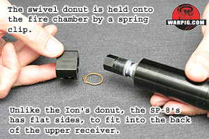 In
case of a leak at the swivel donut, a pair of snap ring pliers can be used
to remove the snap ring and slide the swivel donut off the fire chamber.
After cleaning and inspection of the seals, all of the seals should be
very lightly lubricated before reassembly. Smart Parts recommends
Sl33k, their brand of pneumatic lubricating grease, for all weather operation. In
case of a leak at the swivel donut, a pair of snap ring pliers can be used
to remove the snap ring and slide the swivel donut off the fire chamber.
After cleaning and inspection of the seals, all of the seals should be
very lightly lubricated before reassembly. Smart Parts recommends
Sl33k, their brand of pneumatic lubricating grease, for all weather operation.
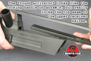 If
necessary for cleaning, the upper receiver halves can be taken apart by
removing the top sight rail, two Phillips head screws and sliding the round
activator forward. Once apart, the feedneck can be removed from the
upper receiver. It should be noted that the feedneck extends over
1.8 inches out of the upper receiver. Because it is a separate piece
it can be cut down to a shorter length for lower profile with feeders like
the Q-Loader or Warp Feed, and if a return to the original length is desired
it can be replaced, without having to replace the entire upper receiver
half. If
necessary for cleaning, the upper receiver halves can be taken apart by
removing the top sight rail, two Phillips head screws and sliding the round
activator forward. Once apart, the feedneck can be removed from the
upper receiver. It should be noted that the feedneck extends over
1.8 inches out of the upper receiver. Because it is a separate piece
it can be cut down to a shorter length for lower profile with feeders like
the Q-Loader or Warp Feed, and if a return to the original length is desired
it can be replaced, without having to replace the entire upper receiver
half.
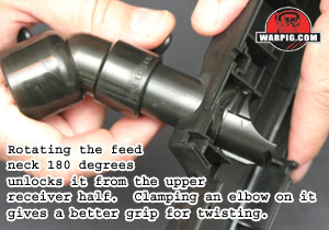 The
feedneck is locked quite securely into the receiver half, but easily unlocks
by rotating it 180 degrees (this can not happen when the SP-8 is assembled
because the body breech fits up to the feedneck, preventing rotation.) The
feedneck is locked quite securely into the receiver half, but easily unlocks
by rotating it 180 degrees (this can not happen when the SP-8 is assembled
because the body breech fits up to the feedneck, preventing rotation.)
All of the components from inside the
upper receiver are reassembled in the reverse of the disassembly procedure,
and the grip frame is reinstalled to the upper receiver the same way.
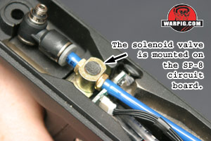
 While
the receiver is off the grip frame the SP-8s circuit board can be slid
out of the top of the grip. This first requires removal of the banjo
bolt on the top of the vertical adaptor (the magazine area of the grip
frame.) Because of the size of the solenoid valve used, it can be
cleaned and checked with relative ease compared to the miniscule valves
found in most electropneumatic paintball guns. While
the receiver is off the grip frame the SP-8s circuit board can be slid
out of the top of the grip. This first requires removal of the banjo
bolt on the top of the vertical adaptor (the magazine area of the grip
frame.) Because of the size of the solenoid valve used, it can be
cleaned and checked with relative ease compared to the miniscule valves
found in most electropneumatic paintball guns.
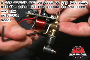 A
metal bracket holds the solenoid together, and is clipped in place by spring
tension. Care must be taken when removing the clip, not to damage
the exposed wires of the solenoid coil. A small hex wrench or tweaker
can be used to pry between the clip and the section of black plastic coil
frame at the top of the solenoid. A
metal bracket holds the solenoid together, and is clipped in place by spring
tension. Care must be taken when removing the clip, not to damage
the exposed wires of the solenoid coil. A small hex wrench or tweaker
can be used to pry between the clip and the section of black plastic coil
frame at the top of the solenoid.
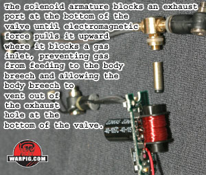 With
the clip removed, the head of the solenoid can be removed and the core
slides easily out of the coil. When reassembling the solenoid, its
head must be oriented correctly. The two hose barbs on the head are
not perfectly aligned, they form a slight angle. This angle should
point, like an arrow, toward the right side of the grip frame when the
circuit board is in place. With
the clip removed, the head of the solenoid can be removed and the core
slides easily out of the coil. When reassembling the solenoid, its
head must be oriented correctly. The two hose barbs on the head are
not perfectly aligned, they form a slight angle. This angle should
point, like an arrow, toward the right side of the grip frame when the
circuit board is in place.
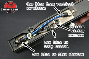
 Smart
Parts has color coded the hoses used in the SP-8 to make reassembly even
easier. The two blue hoses are under constant pressure the gas
feeding from the vertical regulator to the solenoid valve and from the
solenoid valve back to the swivel donut. The clear hose runs from
the solenoid valve to the front body breech, and its gas supply is switched
off and on by the solenoid valve. It is also identified by a small
rubber band keeping the Vision wiring harness bundled to it. Smart
Parts has color coded the hoses used in the SP-8 to make reassembly even
easier. The two blue hoses are under constant pressure the gas
feeding from the vertical regulator to the solenoid valve and from the
solenoid valve back to the swivel donut. The clear hose runs from
the solenoid valve to the front body breech, and its gas supply is switched
off and on by the solenoid valve. It is also identified by a small
rubber band keeping the Vision wiring harness bundled to it.
Continue to Testing
|