  |
|
|
|
|
|
|
| |
|
|
|
|
|
|
What
do you think?
|
by Bill Mills Page 2 With an understanding of the electronics in hand, its time to set up the gun for use. The stock trigger pull of the Matrix is similar to many electropneumatic paintguns. Compared to a mechanical trigger, the pull is shorter and lighter. There is room for improvement though, and the Matrix is built to allow the trigger pull to be adjusted shorter without special custom work or a trigger job. From the factory, the trigger is set a bit longer than needed to ensure the most reliable operation. Tuning to the shortest possible trigger pull makes faster rates of fire easier to attain, but also carries the risk of mis-tuning the trigger to the point that it does not function properly.
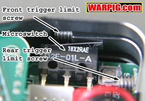
The trigger has two adjuster screws. One adjusts how far back the trigger will pivot, and one adjusts how far forward the trigger will go released. Ideally it should be set so that it stops just after the microswitch clicks, and the forward movement stops just after the microswitch has clicked again on the release.
The way the Matrix ships, adjusting the rear travel limit screw is cumbersome. It has a hex hole in the top, but to test the adjustment, the grip must be installed on the gun, where you can't get to the hex head in the screw. This is because the rear limit screw bumps into the bottom of the receiver to stop the trigger pull. You could adjust, mount the grip, test, unmount the grip, adjust, mount the grip test, etc. until you get it right. Or.... You can unscrew the rear trigger limit screw all the way, flip it upside down, and reinstall it, then reinstall the grip frame on the receiver (being careful not to pinch the wires.) Also note, when reinstalling, that the longer of the two grip frame screws goes in the front. This is easy to remember as the top of the grip frame is thicker in the front than the back.
It is important, when adjusting the rear trigger travel limit screw to make certain that the trigger is stopped before it can come into contact with the body of the microswitch, it must only press on the metal lever of the microswitch. Allowing the trigger to hit the switch itself can crack and destroy the microswitch. Only after adjusting the trigger travel limits where you like them, should you consider adjusting the trigger return spring. Some people choose to cut it down, to weaken the trigger return force, or stretch it to increase it. Some people leave it out all together and rely just on the microswitch to return the trigger. Making the trigger pull short by adjusting the travel stops makes a significant difference in how fast the trigger can be pulled. Lightening the spring doesn't make as much of a difference in speed when the pull is down own to 1 or 2mm in length, but it can cause problems. If the return spring is too weak, the trigger won't return as fast or reliably, and wont be able to shoot as fast. A very lightweight trigger also increases the risk if firing accidentally when the gun is set down or bumped. It is also important to note, that too light and or short of a trigger pull can lead to the trigger firing from the vibration of the Matrix firing leading to rapid fire bursts of shots. Runaway trigger bounce is not legal in most paintball tournaments or at most paintball fields, to it is important to retest the trigger adjustments after the gun is gassed up as well.
When connecting an air system to the vertical regulator, it is vital that the proper port be used. For the original regulator and the newer Custom Products regulator, this is not an issue, as they both have their input at the bottom. For the Centerflag regulator, there are two threaded openings at the top, one for input and one for output. The hose from the compressed air system must go to the input opening. The output opening is a handy place to put a gauge (for review, a Pro-Team Products 0-1200 psi micro-gauge was used) to check the operating pressure of the Matrix. If the gas supply is hooked up to the input side of the regulator, the air will feed into the Matrix at the same pressure supplied by the HPA system. 400 to 800 psi will, in a worst-case scenario, damage the solenoid valve (most possible on an LED Matrix where there is no LPR) but it is more likely to blow out the rear most bolt o-ring, rendering the gun inoperable until it is repaired. Both of these situations can be avoided by paying attention while hooking up the air system.
Also included in the package with the Matrix LCD was a bottle of Battle Lube, the grease recommended by Generation E for lubricating the o-rings inside the bolt assembly. The vertical feed neck of the Matrix LCD is not adjustable, hoppers need to be friction fit. The eVLution II loader used for testing had previously been sanded to fit an Angel IR3, and slid snugly into the Matrix. The rest of the set up was done at the field, at the chrono station. The low-pressure regulator shipping with the Matrix LCD is a PBC regulator. Proper setup involves backing out the adjuster wheel on the LPR before gassing up the paintgun. It should be backed out to the point that it no longer engages its internal spring. This will have the effect of sending no air the solenoid valve. With the air source screwed in (goggles on at the chrono range) and the grip turned on to live, the trigger is pulled, and the regulator adjuster screwed in, about ¼ turn at a time, until the Matrix starts going through a full firing cycle with each trigger pull. Then it was time to shoot paint over the chronograph. The vertical regulator is used to adjust velocity, and two to three shots should be checked after each adjustment, until it is firing close to the field velocity typically 280 feet per second (always under 300 fps.) Then the low pressure adjustment is completed, by backing off the LPR and then turning it in, in 1/8 of a turn increments while taking two or three shots over the chrono until adjustments have less than 5 fps affect on velocity. Once set, a hex screw was used to lock the LPR in place, and then velocity can be given a final minor tweak on the vertical regulator. It is important to note, that any significant change to the velocity made with the vertical regulator will necessitate resetting the LPR to compensate for the new input pressure it is receiving. Further adjustments can be done, changing dwell times and pressure to optimize performance to a particular barrel, especially with barrels which are significantly longer or shorter than the stock barrel, however, for review, the dwell settings were left at the stock 12ms front pulse and 35 ms back pulse, which yields a maximum rate of fire of 22.2 balls per second. Needless to say that rate wasnt achieved on the field.
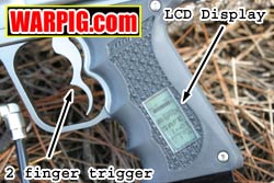
There is a reason the LCD Matrix has
quickly risen in popularity. Its LCD interface gives easy access
to its basic features without losing the user in extra bells, whistles,
and complexity, and it has improved on the flaws of the original Matrix
while retaining its strong points gentle treatment of paint, high speed
and quiet operation.
|
| Copyright © 1992-2019
Corinthian Media Services. WARPIG's webmasters can be reached through our feedback form. All articles and images are copyrighted and may not be redistributed without the written permission of their original creators and Corinthian Media Services. The WARPIG paintball page is a collection of information and pointers to sources from around the internet and other locations. As such, Corinthian Media Services makes no claims to the trustworthiness or reliability of said information. The information contained in, and referenced by WARPIG, should not be used as a substitute for safety information from trained professionals in the paintball industry. |
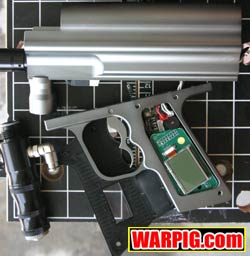
 The
Matrix trigger pivots on a pin that is pressed through the grip frame.
The rear portion of the trigger extends into the grip frame, and when the
trigger is pulled the rear portion pushes up against a microswitch on the
circuit board. This is how the mechanical movement of the trigger
is converted into an electrical pulse. The microswitch makes a definite
clicking sound both when it is actuated, and when it is released.
The clicking sound is helpful in tuning the trigger to the shortest reliable
pull.
The
Matrix trigger pivots on a pin that is pressed through the grip frame.
The rear portion of the trigger extends into the grip frame, and when the
trigger is pulled the rear portion pushes up against a microswitch on the
circuit board. This is how the mechanical movement of the trigger
is converted into an electrical pulse. The microswitch makes a definite
clicking sound both when it is actuated, and when it is released.
The clicking sound is helpful in tuning the trigger to the shortest reliable
pull.
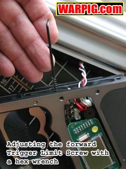 To
adjust the trigger pull, take off the grip frame (degas the gun, unplug
the battery and take off the grip panels the power and solenoid wires
do not need to be removed from the circuit board, the grip only has to
come far enough away to get access to the adjustment screws - be careful
not to stress the wires running between the grip and the receiver,) and
use a small hex wrench to first adjust the release limit screw. Pull the
trigger, and release it and listen for the click. If it can keep going
much further past the point where it clicks, turn the screw inward to shorten
the release stroke. If you go too far, it won't click on the release every
time (or at all) then back the screw out some.
To
adjust the trigger pull, take off the grip frame (degas the gun, unplug
the battery and take off the grip panels the power and solenoid wires
do not need to be removed from the circuit board, the grip only has to
come far enough away to get access to the adjustment screws - be careful
not to stress the wires running between the grip and the receiver,) and
use a small hex wrench to first adjust the release limit screw. Pull the
trigger, and release it and listen for the click. If it can keep going
much further past the point where it clicks, turn the screw inward to shorten
the release stroke. If you go too far, it won't click on the release every
time (or at all) then back the screw out some.
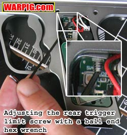 Now,
with the grip panels off, you can adjust the screw, test, adjust, test,
until you get the trigger to stop perfectly right after the microswitch
clicks. At this point it is easiest to adjust with a ball end hex wrench,
otherwise you will have to use the short end of the hex wrench which means
you can only turn 1/4 turn at a time (and which is why they are put in
from the top at the factory - when the grip is off they are easier to access
that way.)
Now,
with the grip panels off, you can adjust the screw, test, adjust, test,
until you get the trigger to stop perfectly right after the microswitch
clicks. At this point it is easiest to adjust with a ball end hex wrench,
otherwise you will have to use the short end of the hex wrench which means
you can only turn 1/4 turn at a time (and which is why they are put in
from the top at the factory - when the grip is off they are easier to access
that way.)
 The
next step in set-up is attaching an air system. For review, a Shocktech
dropforward with ASA was used. Included with the Matrix LCD is a
macroline hose and elbow. A swiveling macroline elbow is already
installed in the vertical regulator, so the other elbow was installed in
the ASA, the hose cut to length, and it was ready to go. Conveniently,
the supplied macroline elbow was pre-coated with thread sealant, avoiding
the need for thread tape or sealant.
The
next step in set-up is attaching an air system. For review, a Shocktech
dropforward with ASA was used. Included with the Matrix LCD is a
macroline hose and elbow. A swiveling macroline elbow is already
installed in the vertical regulator, so the other elbow was installed in
the ASA, the hose cut to length, and it was ready to go. Conveniently,
the supplied macroline elbow was pre-coated with thread sealant, avoiding
the need for thread tape or sealant.
 To
add a little confusion to the mixture, many of the Centerflag regulators
sold with the Matrix are not laser engraved. Some online rumors have
implied that these regulators are knock-offs. They are not.
They are genuine Centerflag regulators but, the engraving was left off
due to a miscommunication between Generation E and Centerflag. When
looking at the regulator while it is mounted, ASA end up, adjuster down,
facing the blow-out disk in the center (the small copper disk held in by
a hollow hex-nut) the high pressure side which should receive the hose
from the air system will be on the left, and the low pressure side that
will be plugged with a hex screw, or hold a gauge will be on the right.
To
add a little confusion to the mixture, many of the Centerflag regulators
sold with the Matrix are not laser engraved. Some online rumors have
implied that these regulators are knock-offs. They are not.
They are genuine Centerflag regulators but, the engraving was left off
due to a miscommunication between Generation E and Centerflag. When
looking at the regulator while it is mounted, ASA end up, adjuster down,
facing the blow-out disk in the center (the small copper disk held in by
a hollow hex-nut) the high pressure side which should receive the hose
from the air system will be on the left, and the low pressure side that
will be plugged with a hex screw, or hold a gauge will be on the right.
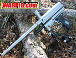 In
action, the Matrix LCD was easy to shoot quickly, and provided nice tight
shot groupings. Notable, is its sound, or lack there of. It
is a relatively quiet paintgun, and especially in the woods, this proved
beneficial to staying concealed while sniping into clearings. With
the lower peak voltage of the rechargeable NiMH battery, it did not fare
well, and was quickly replaced with an alkaline battery which yielded long
life in the gun.
In
action, the Matrix LCD was easy to shoot quickly, and provided nice tight
shot groupings. Notable, is its sound, or lack there of. It
is a relatively quiet paintgun, and especially in the woods, this proved
beneficial to staying concealed while sniping into clearings. With
the lower peak voltage of the rechargeable NiMH battery, it did not fare
well, and was quickly replaced with an alkaline battery which yielded long
life in the gun.