  |
|
|
|
|
|
|
| |
|
|
|
|
|
|
What
do you think?
|
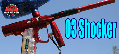
03 Shocker
Smart Parts followed up the PVI Shocker with the more popular Shocker Sport and later Shocker models. The Shocker was the flagship paintgun of Smart Parts factory team the All Americans (now known as the Philly Americans.) While limited by internal gas flow to an 11.2 bps firing rate, the Shocker held popularity with a reputation for accuracy, quiet operation, and the ability to handle fragile paint well with its low-pressure operation. Opponents of the Shocker didnt care for its size, shape and weight, often calling it a brick with a handle, or a shoebox with a barrel. Smart Parts later paintgun, the Impulse drew much attention away from the aging Shocker design with its higher speed open bolt operation.
The Shocker 03 body is a single-tube layout. While exact diameters vary at points on the body with different milling patterns, it rises roughly an inch and a half above the grip frame and is approximately one and three eighths of an inch wide. In terms of operation the new Shocker is much simpler than its predecessor. Instead of utilizing separate solenoid valves to operate the guns pneumatically driven bolt and shuttle valve, the new design uses a single solenoid to control a spool valve. The spool valves core also serves as the paintguns bolt, allowing the bulk and mechanical complexity of the second solenoid valve to be done away with. Gas enters the Shocker 03 through a vertical ASA, typically equipped with a vertical regulator. This reg drops the pressure to drive the Shocker at under 200 psi. The same gas source is used for both controlling the valve and firing the ball. From the vertical ASA, the gas travels through gas paths in the body of the gun. One tube channels gas into the Shocker valves firing chamber. This is an area within the valve that functionas as a reservoir, to hold the gas which will fire the ball. Gas is also supplied to the solenoid valve. This compact, electronically actuated valve acts as a pilot valve for the Shockers main valve. Because the spool at the core of the Shockers valve also acts as the bolt, the entire valve assembly is often simply referred to as the bolt assembly. When the Shockers electronics activate the solenoid valve, it redirects gas flow to move the bolt forward.
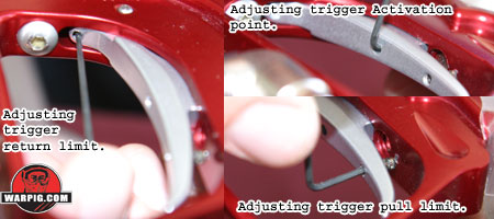
The Shocker 03 trigger utilizes a magnetic repulsion return system and four adjustment points so that it can be adjusted to a wide variety of feels. It is a smooth design with rounded edges and a gentle curve near its lower end. It varies in width from approximately 5/16 inches at the top to 1/8 inch at the bottom.
Three of the triggers adjustment screws can be accessed without disassembling the paintgun, making it very simple to test changes while adjusting. At the top of the trigger, a .050 hex screw limits the forward travel of the trigger, and near the bottom, another limits the triggers rear travel. With these two screws alone the trigger can be adjusted from the stock pull of 4 or more millemeters down to 1 millemeter or less measured at the base of the trigger. The third outside adjuster screw lies in the center of the trigger. This screw adjusts the triggers interaction with the internal micro-switch, and is a feature not found on most paintguns. Adjusting this screw can affect where in the trigger pull cycle the micro-switch is actuated. This is most useful if switching to a custom switch, or performing a popular trigger modification that involves inverting the position of the stock switch. The 3 main trigger adjustment points allow for the trigger pull to be adjusted in minutes without taking the Shocker apart. With only these three adjustments, a trigger pull can be achieved which is better than what was normal for custom trigger jobs performed by airsmiths on paintguns in the mid 1990s. The fourth adjustment is more difficult to access. It is the trigger pull weight adjustment. The Shocker 03 does not use springs to return the trigger to its rest position. Instead a rare earth magnet in the grip frame repels a tiny rare earth magnet in the trigger. The position of this magnet, in its threaded mount affects the strength of the trigger return force. When the magnet is closer to the trigger, the repulsing force is stronger, when it is further away it is weaker. While the return strength is possible to adjust, it requires punching out dowel pins to release the trigger switch and circuit board to have access to the back-side of the magnet. While this is a simple task for an airsmith, it may be a bit of a challenge for the average user.
Most paintguns regardless of open or closed bolt design, which utilize an o-ring seal around the front of the bolt put that o-ring on the front of the bolt. With the Shocker 03, Smart Parts has placed that o-ring inside the receiver. This placement reduces the regular wear seen by a bolt front o-ring, because the time of contact between moving parts is greatly reduced. It also decreases bolt friction meaning less gas pressure is needed to move the bolt back and forth. Additionally, because it puts a wider clearance between the bolt and sidewalls around the feedport area, there is less of a chance of bolt stick due to debris in the breech. On either side of the breech are ball detents. The ball detents protrude into the breech area and prevent a ball from rolling forward into the barrel, which would allow a second ball to load behind it. These spring loaded synthetic ball bearings are held inside aluminum mounting bolts, and can be removed for cleaning as a single assembly with a 1/8 inch hex wrench. The right hand ball detent assembly serves a second function. It holds the cover plate for the Shocker Vision system.
The Shocker 03 feedneck is of a low profile design, and a tight enough fit that many aftermarket high-end loaders like the HALO and eVLution require sanding for a proper fit. The neck is threaded into the receiver with the same thread style as Smart Parts other paintguns, allowing for a variety of aftermarket clamping feed neck options to be installed as upgrades. Continued on Page
2.
|
| Copyright © 1992-2019
Corinthian Media Services. WARPIG's webmasters can be reached through our feedback form. All articles and images are copyrighted and may not be redistributed without the written permission of their original creators and Corinthian Media Services. The WARPIG paintball page is a collection of information and pointers to sources from around the internet and other locations. As such, Corinthian Media Services makes no claims to the trustworthiness or reliability of said information. The information contained in, and referenced by WARPIG, should not be used as a substitute for safety information from trained professionals in the paintball industry. |

 In
the summer 1996, the International Amateur Open was host, as it has been
for many years, to a paintball industry conference. In past years,
that industry conference was one of the main places that new products for
the sport of paintball were unveiled, during the events new product parade.
At many such product launchings there are items that are add-ons, accessories,
or re-hashes of another product that has been on the market for years.
At the 1996 conference, both the PVI Shocker distributed by Smart Parts
and the WDP Angel distributed by Brass Eagle were introduced. These
paintguns were the earliest mass produced electropneumatic paintguns to
be used in upper level tournament play in the United States, and ushered
in a paradigm shift in the definitions of tournament level paintgun.
In
the summer 1996, the International Amateur Open was host, as it has been
for many years, to a paintball industry conference. In past years,
that industry conference was one of the main places that new products for
the sport of paintball were unveiled, during the events new product parade.
At many such product launchings there are items that are add-ons, accessories,
or re-hashes of another product that has been on the market for years.
At the 1996 conference, both the PVI Shocker distributed by Smart Parts
and the WDP Angel distributed by Brass Eagle were introduced. These
paintguns were the earliest mass produced electropneumatic paintguns to
be used in upper level tournament play in the United States, and ushered
in a paradigm shift in the definitions of tournament level paintgun.
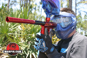 The
Shocker 03 changes all of that. While it bears the same name as its
predecessor, and low pressure operation, how it works, how it looks, and
the way it performs on the field, are a whole new paintgun. The Shocker
03 is lighter, sleeker and faster.
The
Shocker 03 changes all of that. While it bears the same name as its
predecessor, and low pressure operation, how it works, how it looks, and
the way it performs on the field, are a whole new paintgun. The Shocker
03 is lighter, sleeker and faster.
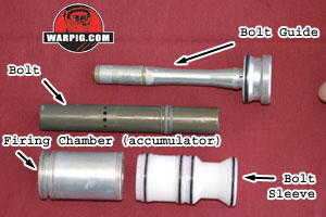 The
Shockers bolt has a raised ridge with a seal in its center. To use
the same terminology as other spool valve designs, this ridge and seal
is referred to as a sail. When combined with a sleeve that fits over
it, this allows it to act as a pneumatic cylinder or piston. When
gas pressure is applied to the back-side of the sail, the bolt is driven
forward, pushing a paintball into the back of the barrel, and sealing the
breech. When the bolt has reached the forward end of its stroke,
it also performs its function as the spool of the Shockers valve, and
allows air to flow from the reservoir into the barrel, propelling the paintball.
Once the ball is fired the circuit board stops energizing the solenoid
valve, which then directs air to the front of the bolts sail, venting
the rear, returning it to the open position. While at rest between
shots, the bolt remains open to allow time for a paintball to be fed into
the breech, and for air to refill the reservoir.
The
Shockers bolt has a raised ridge with a seal in its center. To use
the same terminology as other spool valve designs, this ridge and seal
is referred to as a sail. When combined with a sleeve that fits over
it, this allows it to act as a pneumatic cylinder or piston. When
gas pressure is applied to the back-side of the sail, the bolt is driven
forward, pushing a paintball into the back of the barrel, and sealing the
breech. When the bolt has reached the forward end of its stroke,
it also performs its function as the spool of the Shockers valve, and
allows air to flow from the reservoir into the barrel, propelling the paintball.
Once the ball is fired the circuit board stops energizing the solenoid
valve, which then directs air to the front of the bolts sail, venting
the rear, returning it to the open position. While at rest between
shots, the bolt remains open to allow time for a paintball to be fed into
the breech, and for air to refill the reservoir.
 Controlling
the solenoid valve is the Shockers circuit board, the electronic brains
of the gun. The circuit sits in the grip frame and draws its power
from a standard alkaline 9-volt battery next to it. As input, the
circuit board is wired to its power switch, a micro-switch activated by
the trigger, and optionally to an infrared eye system in the breech.
Because the battery power is used to drive a very small solenoid valve,
the Shocker 03 can achieve quite long battery life. Changing the
battery is simply a matter of removing two Phillips head screws and opening
one of the grip panels to expose it. The battery can be twisted for
removal, and a fresh one reinstalled in its place.
Controlling
the solenoid valve is the Shockers circuit board, the electronic brains
of the gun. The circuit sits in the grip frame and draws its power
from a standard alkaline 9-volt battery next to it. As input, the
circuit board is wired to its power switch, a micro-switch activated by
the trigger, and optionally to an infrared eye system in the breech.
Because the battery power is used to drive a very small solenoid valve,
the Shocker 03 can achieve quite long battery life. Changing the
battery is simply a matter of removing two Phillips head screws and opening
one of the grip panels to expose it. The battery can be twisted for
removal, and a fresh one reinstalled in its place.
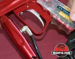 The
trigger guard surrounding the trigger is allows easy room for two gloved
fingers, but is angled back along its front edge. While the front
edge angle may seem insignificant at first, it means that the vertical
regulator can be unscrewed and removed for replacement or cleaning without
first taking the macroline fitting off of the regs side. When screwed
in completely the macroline fitting lies between the reg and the guard,
so that it does not get in the way of a hand using the regulator as a fore
grip.
The
trigger guard surrounding the trigger is allows easy room for two gloved
fingers, but is angled back along its front edge. While the front
edge angle may seem insignificant at first, it means that the vertical
regulator can be unscrewed and removed for replacement or cleaning without
first taking the macroline fitting off of the regs side. When screwed
in completely the macroline fitting lies between the reg and the guard,
so that it does not get in the way of a hand using the regulator as a fore
grip.
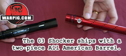 At
the front end of the Shocker are the barrel mounting threads. The
Shocker 03 accepts standard Shocker threaded barrels. The gun ships
with a two-piece All American barrel. Because Smart Parts now puts
a standardized threaded connection on all of their two piece barrels, the
All American front can be combined with a Freak back for paint to barrel
size matching, or a different style of tip can be mounted on the stock
barrel back.
At
the front end of the Shocker are the barrel mounting threads. The
Shocker 03 accepts standard Shocker threaded barrels. The gun ships
with a two-piece All American barrel. Because Smart Parts now puts
a standardized threaded connection on all of their two piece barrels, the
All American front can be combined with a Freak back for paint to barrel
size matching, or a different style of tip can be mounted on the stock
barrel back.
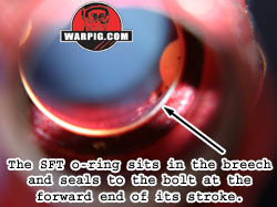 Further
into the receiver lies what Smart Parts calls the SFT o-ring. While
most airsmiths would refer to the Shocker 03 as an open bolt design, because
the bolt is in the rear, open position at rest between shots, Smart Parts
uses the term Seal Forward Technology or SFT, referring to the fact that
the bolt seals the rear of the breech before firing the jet of compressed
gas that will propel the paintball.
Further
into the receiver lies what Smart Parts calls the SFT o-ring. While
most airsmiths would refer to the Shocker 03 as an open bolt design, because
the bolt is in the rear, open position at rest between shots, Smart Parts
uses the term Seal Forward Technology or SFT, referring to the fact that
the bolt seals the rear of the breech before firing the jet of compressed
gas that will propel the paintball.
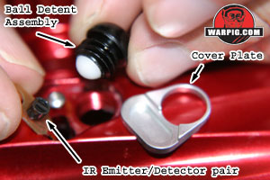 The
Vision system is an optional feature on the Shocker 03. Behind the
cover plate on Vision equipped Shockers is a small flexible printed circuit
with a matched infrared emitter-detector pair. The emitter shines
infra-red light into the breech, and the detector allows electrical current
to pass through it based on the amount of infra-red light that is reflected
back into it. The steel cover allows easy access to the eye for
cleaning in case it is fouled by paint or debris. A small hex screw
holds the vision circuit in place and must be removed to pull out and clean
the sensors. The vision wiring passes through a channel in the bottom
of the receiver where it connects to a circuit board mounted on the solenoid
valve.
The
Vision system is an optional feature on the Shocker 03. Behind the
cover plate on Vision equipped Shockers is a small flexible printed circuit
with a matched infrared emitter-detector pair. The emitter shines
infra-red light into the breech, and the detector allows electrical current
to pass through it based on the amount of infra-red light that is reflected
back into it. The steel cover allows easy access to the eye for
cleaning in case it is fouled by paint or debris. A small hex screw
holds the vision circuit in place and must be removed to pull out and clean
the sensors. The vision wiring passes through a channel in the bottom
of the receiver where it connects to a circuit board mounted on the solenoid
valve.
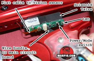 The
use of the circuit board mounted on the solenoid valve as a junction means
that only one cable connects the grip frame to the receiver, making disassembly
more modular. The protected path for the Vision wiring not only prevents
damage, but also keeps the aesthetic lines of the receiver intact.
There is no need for cover plates or panels to guard external wiring.
The
use of the circuit board mounted on the solenoid valve as a junction means
that only one cable connects the grip frame to the receiver, making disassembly
more modular. The protected path for the Vision wiring not only prevents
damage, but also keeps the aesthetic lines of the receiver intact.
There is no need for cover plates or panels to guard external wiring.