  |
|
|
|
|
|
|
| |
|
|
|
|
|
|
What
do you think?
|
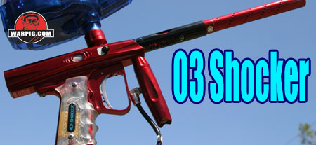
03 Shocker
Continued from Page1 Traveling further back along the stock receiver one finds a view window, which exposes a portion of the bolt assembly. This feature allows aftermarket or upgrade bolt assemblies to be identified by color or other markings.
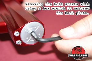
Further back along the receiver is the rear cap. This is the piece which holds the entire bolt assembly in place, and it consists not only of the rear cap of the receiver, but also as a central bolt guide which seals off portions of the bolts interior. Using a hex wrench, the rear cap can be easily removed (only when the Shocker 03 is completely de-gassed) and extracted.
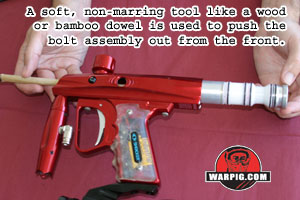
Pulling the bolt guide out by the rear cap will likely leave the remaining valve components inside the receiver due to friction. Pushing from the front with a finger (if one is blessed with a long, thin enough finger, like E.T.) or a something of a soft, non-marring material like a wooden dowel will allow for removal of the remaining components. The valve bolt assembly consists of the rearcap/bolt guide, the bolt, the bolt sleeve, and the firing chamber or chamber (the reservoir that fills with air for each shot.)
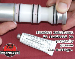
After removal for cleaning or inspection, the seals on the valve/bolt assembly should be lubricated with Smart Parts Included Shocker Lubricating Grease.
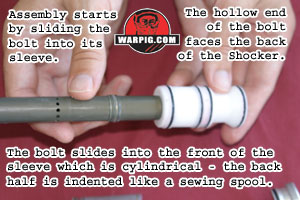
Re-assembly follows a simple pattern. With the front of the bolt facing to the left, the bolt sleeve is held with its indented half on the right. The bolt slides into the bolt sleeve from left to right.
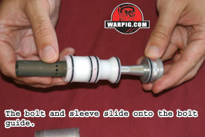
The bolt can then be slid onto the bolt guide, also from left to right.
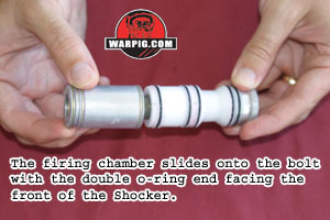
The firing chamber then slides over the front of the bolt from the left, with the double o-ring end on the left.
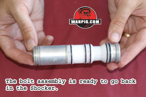
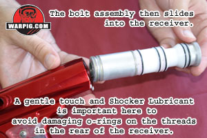
The full assembly can then be slid back into the Shocker 03 body, and screwed into place.
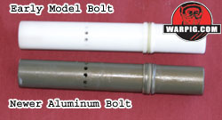
Aside from materials, the newer aluminum bolt is nearly identical to the earlier model. The exception is that on the front of the bolts sail has a bumper in place to cushion its impact against the rear of the firing chamber.
When the Shocker is off, pressing and holding the button for approximately three seconds is rewarded by a chirping sound to indicate that the Shocker is on. At this point the LED will blink in double pulses about once per second the Shocker is live and will fire when the trigger is pulled. A short press on the button, and the Shocker will activate the Vision circuitry. At this point, after the first shot fired, it will not fire unless it detects a paintball in place ready to be chambered. The LED will blink rapidly if a ball is in place, and slowly if the breech is empty. Pressing the button again, will de-activate Vision mode. In either Vision or non-Vision modes, pressing and holding the button for about three seconds will turn the Shocker 03 off.
Dwell, or the amount of time that the solenoid valve is energized for each shot is adjusted simply by pressing the adjuster buttons with the power on. Each time one of the buttons is pressed, the circuits speaker will chirp indicating that the timing has been increased or decreased by 0.25 milliseconds. The dwell is adjustable between 3 and 14 milliseconds, the circuit board will chirp repeatedly when the minimum value is reached. Setting to a specific value involves stepping it down to the minimum, and then counting up to the desired value. Adjusting the recharge time changes the amount of time the Shocker will wait after firing a shot before firing the next shot. The recharge value is important in that without a Vision system in place, it will be what determines that the bolt is open long enough for a ball to fall into place, in addition to making sure the bolt is back long enough for the air reservoir to recharge for the next shot to achieve full velocity. The recharge time is also adjusted with the same two buttons, but done while the trigger is pulled and being held. The recharge is adjustable over a much wider range thirty to seventy milliseconds, in one millisecond intervals. While adjusting dwell and recharge time may seem a little tricky it is fortunately not necessary for normal use of the Shocker 03. Adjusting the timing comes in to play for fine tuning when attempting to maximize the number of shots available per tank fill, or when adjusting for optimal operation after changing to a different bolt/valve kit. The combination of the Dwell and Recharge times results in the total time needed for each shot, which directly sets the Shockers maximum rate of fire.
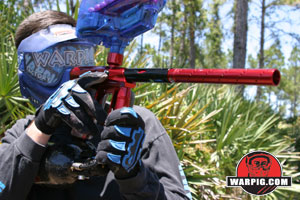
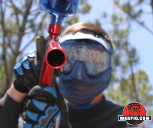
On the field at Hurricane Paintball Park in Palm Bay, Florida, the Shocker 03 was trouble free, fast firing, quiet and accurate. Its lightweight and compact form factor made it easy to use and highly mobile in the woods or on the speedball field. While some paintgun manufacturers have moved toward adding more interface features, more modes of fire, and more of those types of bells and whistles, the semi-only operation and one button control of the Shocker 03 made it easy for players who had never seen it before to try it out without needing to spend time reading through a manual. Luxury cars may offer features like DVD players, lots of knobs, dials and GPS navigation, but like a race-car with little more than a tachometer and oil pressure gauge, the controls of the Shocker 03 offered functional simplicity and ease of use on the field. Shot groupings were tight, and the short, light trigger pull made high rates of fire easy to achieve. Through game use, the Vision mode was activated, and ball breakage was not a problem.
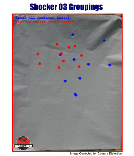
Off the field, on the test stand, the Shocker 03 was tested for velocity consistency and target groupings under a variety of conditions.
Target groupings were fired at 75 feet, again with both the stock and size matched Freak. Groupings of ten shots were fired with one-second intervals between shots, to allow comparison of grouping sizes. Predictably, the matched bore size yielded a tighter grouping.
An additional velocity consistency comparison
was made between slow and rapid firing to find fluctuations caused by valve
and regulator recharge rates. With the size matched Freak Barrel,
three strings of ten shots were fired at one second intervals followed
by three groups of 10 shots fired at a rate of fourteen balls per second.
During the rapid fire strings the Shocker only fired 26 shots over the
30 trigger pulls, indicating that the Vision system had prevented ball
breaks from paint that had not fully loaded into the breech. Comparing
the data from the six strings, the low speed firing did provide a slightly
more consistent velocity, with a standard deviation of 3.4 compared to
4.6. However the average velocity of the low rate of fire string
was 299.2 feet per second, compared to 299.4 for the high rate of fire
string, a very slight increase, indicating that shoot down under typical
rapid fire is not a problem for the 03 Shocker running a Max Flo air system.
|
| Copyright © 1992-2019
Corinthian Media Services. WARPIG's webmasters can be reached through our feedback form. All articles and images are copyrighted and may not be redistributed without the written permission of their original creators and Corinthian Media Services. The WARPIG paintball page is a collection of information and pointers to sources from around the internet and other locations. As such, Corinthian Media Services makes no claims to the trustworthiness or reliability of said information. The information contained in, and referenced by WARPIG, should not be used as a substitute for safety information from trained professionals in the paintball industry. |

 It
is important to note that the original bolt, manufactured of white Delrin
like material was replaced in later models with an aluminum bolt.
The aluminum bolt, and a replacement power switch button are available
as a factory update from Smart Parts for owners of Shocker 03s with serial
numbers ranging from 0000 to 3900. This is a free update that can
be obtained by filling out a form on the Smart Parts web site.
It
is important to note that the original bolt, manufactured of white Delrin
like material was replaced in later models with an aluminum bolt.
The aluminum bolt, and a replacement power switch button are available
as a factory update from Smart Parts for owners of Shocker 03s with serial
numbers ranging from 0000 to 3900. This is a free update that can
be obtained by filling out a form on the Smart Parts web site.
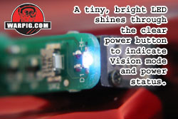 Beneath
the receiver on the back of the Shockers grip frame is the power button.
This is a clear push-button which activates a momentary switch on the solenoid
mounted circuit board. Also on the same circuit board is a very small,
yet very bright blue light emitting diode, or LED. The push-button
is made from clear plastic, which transmits the light from the LED.
This plastic piece is the other part in the factory upgrade for owners
of earlier production Shocker 03 paintguns. The new piece is more
robust. A pair of tiny magnets fit into arms on the plastic button
and pull it against a steel dowel pin, instead of using spring or other
return mechanism.
Beneath
the receiver on the back of the Shockers grip frame is the power button.
This is a clear push-button which activates a momentary switch on the solenoid
mounted circuit board. Also on the same circuit board is a very small,
yet very bright blue light emitting diode, or LED. The push-button
is made from clear plastic, which transmits the light from the LED.
This plastic piece is the other part in the factory upgrade for owners
of earlier production Shocker 03 paintguns. The new piece is more
robust. A pair of tiny magnets fit into arms on the plastic button
and pull it against a steel dowel pin, instead of using spring or other
return mechanism.
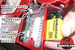 Two
buttons on the inside of the grip frame are used to adjust the timing values
in the Shockers internal memory. Accessing the buttons requires
using a Phillips screwdriver to remove two screws and opening the left
hand side of the wraparound grip. Whether adjusting the dwell time
or the recharge time, the top button increasing the timing value, and the
lower button decreases the timing value.
Two
buttons on the inside of the grip frame are used to adjust the timing values
in the Shockers internal memory. Accessing the buttons requires
using a Phillips screwdriver to remove two screws and opening the left
hand side of the wraparound grip. Whether adjusting the dwell time
or the recharge time, the top button increasing the timing value, and the
lower button decreases the timing value.
 The
Shocker 03 used for review was bundled from the factory with a Max Flo
compressed air system, with a 68 cubic inch compressed air tank.
Field testing was performed with a HALO B loader, as recommended in the
Shocker 03 manual. The stock barrel was used, as well as a Freak
with All American tip, using the .687 insert, which matched, by blow testing
the DraXxus Hellfire paint used for testing.
The
Shocker 03 used for review was bundled from the factory with a Max Flo
compressed air system, with a 68 cubic inch compressed air tank.
Field testing was performed with a HALO B loader, as recommended in the
Shocker 03 manual. The stock barrel was used, as well as a Freak
with All American tip, using the .687 insert, which matched, by blow testing
the DraXxus Hellfire paint used for testing.


 The
Shocker 03 combines the accuracy, quiet operation and ability to handle
brittle paint that were hallmarks of the original Shocker with a compact,
lightweight form factor and high rate of fire. It is streamlined
not only in appearance, but also in operation giving tournament legal semi-automatic
mode and a simple to use control interface. It is the Shocker reborn.
The
Shocker 03 combines the accuracy, quiet operation and ability to handle
brittle paint that were hallmarks of the original Shocker with a compact,
lightweight form factor and high rate of fire. It is streamlined
not only in appearance, but also in operation giving tournament legal semi-automatic
mode and a simple to use control interface. It is the Shocker reborn.